Our Methods

Experts in Utility Locating and Geophysical Surveying

Electrical Resistivity

Spectrum specializes in the utilization of electrical resistivity tomography (ERT) and electrical resistivity imaging (ERI), along with induced polarization (IP), for groundwater applications. These applications include the delineation of preferential pathways for groundwater, delineation of aquifers and aquicludes for well siting, and delineation of saline/high TDS/contaminant plumes in groundwater.

The electrical resistivity of a material is a measure of the ability of that material to transmit an electrical current. In the electrical resistivity method a DC circuit is established in the ground via cables and electrodes, and the ground acts as the resistor to complete the circuit. There are several different arrays that can be used to collect the data; however, the most common are Wenner, Schlumberger and dipole-dipole. Electrical resistivity data are typically displayed in 2D sections or profiles where they supply lateral and vertical electrical resistivity information about materials either directly below a given transect (much like a road cut); or between two boreholes.

The electrical resistivity method had its beginnings in the mining industry, but is now commonly used in the environmental and engineering businesses. Because the electrical resistivity of a material correlates well with grain size (and generally increases with increasing grain size) this method can be used not only to identify lateral and vertical boundaries between different materials but also to identify the lithology of the material. The electrical resistivity method is also sensitive to the chemistry of a material, and therefore can be used for many groundwater applications such as the delineation of saltwater and contaminant plumes (DNAPL and LNAPL), delineation of zones of weathered or fractured rock in competent rock, and delineation of degree of saturation of permeable materials. Because boundaries between electrical layers often correlate well with geologic contacts, the electrical resistivity method has many applications

Frequency Domain Electromagnetics

The frequency domain method uses the inductive properties of a continuous primary electromagnetic field to measure the conductivity (reciprocal of resistivity) of the material through which the field passes. This method has a long history in the mining industry for exploration of base metal deposits; however, it is now used for many environmental and engineering types of applications. Land-based frequency domain methods have 40 years of demonstrated use for the delineation of undocumented disposal, chemical waste and large buried metallic objects. Because the material of which the subsurface is composed controls the ability of the subsurface to carry an electrical current (or hold a secondary field), the conductivity of a material correlates well with grain size (and generally increases with decreasing grain size) these methods can be used to both identify lateral boundaries between different materials and lithology of the materials. Frequency domain methods are also highly sensitive to the chemistry of materials, and therefore can be used for many groundwater applications such as the delineation of shallow high-TDS and contaminant plumes (DNAPL and LNAPL) and the delineation of weathered, altered, or vertical water-bearing zones in bedrock.

In addition, these methods are very sensitive to metallic material, and can be used to detect metallic pipes, USTs and drums. With the aid of a regularly spaced grid, these methods can be used to distinguish the boundaries between contrasting materials with a very high degree of resolution. Frequency domain methods are particularly useful where there is a large area to investigate, as an extremely large number of measurements can be made quickly and cost effectively. For shallow applications Spectrum uses a Geonics EM-31 terrain conductivity meter (EM-31); for deeper applications Spectrum uses a Geonics EM-34-3 terrain conductivity meter (EM-34).

This method can be used for determination of lateral boundaries of a landfill, delineation of contaminant plumes, placement of water wells and delineation of geologic contacts.

Time Domain Electromagnetics

The time domain method is a method that uses the inductive properties of a transient primary electromagnetic field to measure the ground response or resistivity of the material through which the field passes after the primary field is turned off. This method has its history in mineral exploration; however, it is now used for many environmental and engineering types of applications. For shallow applications Spectrum uses the Geonics EM-61 MK-2 high sensitivity metal detector (EM-61). This instrument is highly effective for the lateral delineation of metallic objects ranging in size from 3-inch military ordnance to 300-foot-long utilities, and can detect a buried 55-gallon drum under up to 9 feet of cover under favorable conditions. The EM-61 is particularly useful where there is a large area to investigate, as an extremely large number of measurements can be made quickly and cost effectively. The EM-61 is very effective in open areas of industrial sites such as chemical plants, refineries and tank farms or at demolished facility locations where no surface expression of the former buildings or utilities exist and utility location using standard methods is very limited.

For deeper applications Spectrum uses the Geonics EM-47 or EM-57 TEM system. These instruments measure the vertical resistivity variation of subsurface materials, and are capable of imaging to significant depths. TEM methods are useful for the vertical delineation of geologic or hydrogeologic contacts in cases where the target is conductive and there is a strong contrast in electrical resistivity (or conductivity – its reciprocal) between one unit and the next. As such, TEM methods are effective for the delineation of sand/shale or sand/clay interfaces or the interface between freshwater and saltwater or freshwater and high-TDS-water aquifers. TEM methods using the EM-47/57 system are especially useful for sites where the space available is small (precludes the use of electrical resistivity), the target is deep (200 feet to 500 feet or more), or for sites where there is a large area to investigate and a limited budget, as many 1D measurements can be made quickly and relatively cost-effectively. In addition, lateral delineation of geologic or hydrogeologic features can be accomplished by stringing together several 1D TEM measurements in a linear fashion to create electrical cross sections.

This method can be used for location of metallic utilities, location of metallic USTs and buried drums, delineation of high-TDS or saline groundwater and placement of water wells.

Refraction Microtremor (ReMi)

The ReMi method is a seismic surface wave method (similar to SASW and MASW methods) that uses ambient noise and surface waves to generate a detailed vertical shear wave velocity (Sv) profile to depths of up to 100 meters. Prior to 1999, seismic shear wave profiles were obtained using shear wave refraction, seismic cone penetrometer, or downhole/crosshole techniques. Downhole and crosshole techniques tend to be more reliable but can be costly. The ReMi technique provides a non-invasive way of obtaining a vertical profile of the shear wave and, unlike borehole methods, this technique provides a shear wave sample of a greater volume of material, thereby allowing a more representative shear wave velocity column that is averaged over the length of the seismic array.

The ReMi method is capable of detecting thin layers and velocity inversions, and as such is highly reliable and commonly used to measure Vs30 for earthquake design ground motion determinations. ReMi can also be used at any site to measure the lateral variation of shear wave velocity in near surface materials. Because it thrives in noisy environments the ReMi method is ideal for shear wave profiling in urban environments where seismic refraction is precluded because of large amounts of ambient noise. Additionally, the ReMi method is also very useful for stratigraphic delineation in complex geologic environments where even shear wave refraction fails.

The hallmarks of the ReMi technique are 1) that it uses a linear array that does not require CMP-style shooting and 2) that it relies primarily on ambient noise to generate the Rayleigh waves.

Magnetics

The magnetics method is a surface method that uses the response of either magnetic materials or atomic particles to an external magnetic field in order to measure the lateral variation in the intensity of the earth’s magnetic field. Because of its sensitivity to ferromagnetic (steel) objects and its great depth of detection, the most common shallow use for this method is to detect buried steel objects, such as USTs, abandoned steel-cased wells and steel piping. However, this method can also be useful for the lateral delineation of certain types of igneous bedrock, and so may be used to identify lateral geologic contacts as well as structural features in these rocks under certain conditions. The magnetics method is particularly useful where there is a large area to investigate, as an extremely large number of measurements can be made quickly and cost effectively.

For most magnetics applications Spectrum uses a Geometrics-858 cesium vapor walking magnetometer (G-858) or a G-858-G cesium vapor walking gradiometer to collect magnetics data. Further investigation of anomalies is often done using a Schonstedt model GA-72CD hand-held magnetic locator.

Electrical Resistivity

Spectrum specializes in the utilization of electrical resistivity tomography (ERT) and electrical resistivity imaging (ERI), along with induced polarization (IP), for groundwater applications. These applications include the delineation of preferential pathways for groundwater, delineation of aquifers and aquicludes for well siting, and delineation of saline/high TDS/contaminant plumes in groundwater.

The electrical resistivity of a material is a measure of the ability of that material to transmit an electrical current. In the electrical resistivity method a DC circuit is established in the ground via cables and electrodes, and the ground acts as the resistor to complete the circuit. There are several different arrays that can be used to collect the data; however, the most common are Wenner, Schlumberger and dipole-dipole. Electrical resistivity data are typically displayed in 2D sections or profiles where they supply lateral and vertical electrical resistivity information about materials either directly below a given transect (much like a road cut); or between two boreholes.

The electrical resistivity method had its beginnings in the mining industry, but is now commonly used in the environmental and engineering businesses. Because the electrical resistivity of a material correlates well with grain size (and generally increases with increasing grain size) this method can be used not only to identify lateral and vertical boundaries between different materials but also to identify the lithology of the material. The electrical resistivity method is also sensitive to the chemistry of a material, and therefore can be used for many groundwater applications such as the delineation of saltwater and contaminant plumes (DNAPL and LNAPL), delineation of zones of weathered or fractured rock in competent rock, and delineation of degree of saturation of permeable materials. Because boundaries between electrical layers often correlate well with geologic contacts, the electrical resistivity method has many applications

Utility Location/Borehole Investigation

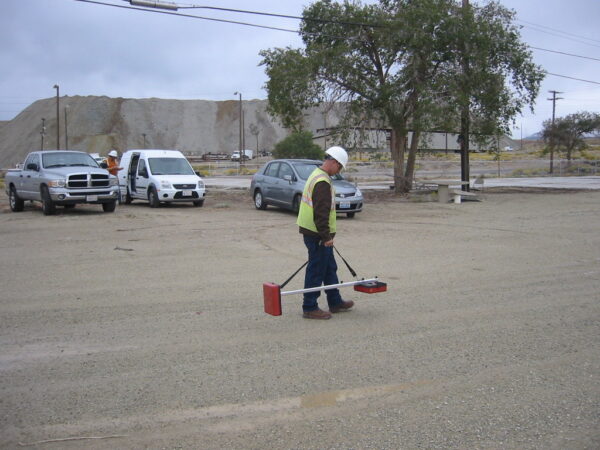
The utility location method is a surface method that uses electromagnetic induction to locate and delineate long, linear metallic or conductive pipes and cables. This method is used in an effort to identify the surface trace of detectable underground utilities and abandoned piping for a variety of environmental and engineering investigations. These utilities include but are not limited to: electric, water, telephone, natural gas, storm drain, sanitary sewer, fuel piping and compressed air.

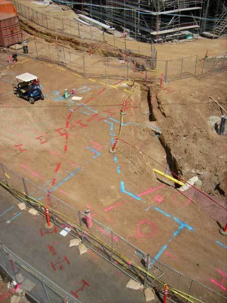
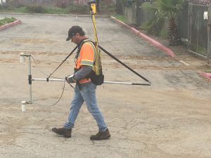
Utility locators may be operated in either active or passive mode. Passive locating is possible when electrically conductive conduits are energized by ambient radio frequencies (RF) that are often produced by 50/60 cycle electrical, radio, audio, television, and communication transmissions. Active locating is initiated by connecting to an exposed conduit and propagating an EM signal at a known frequency (8 and 33 kHz for example) along the conduit. A receiver, tuned to these frequencies, is then used to locate the signal maxima (or surface trace) of the applied signal. Spectrum uses a Radio Detection 7000 transmitter w/ matched receiver, Fisher TW-6 M-scope shallow focus metal detector (M-Scope), and Dynatel 500A transmitter w/ matched receiver, among other instruments, for utility location. Once located, utilities are marked on the ground with surveyor’s chalk using the American Public Works Association color code found below.