Passive and active EM utility-locating methods are used in an effort to identify the surface trace of detectable underground utilities and abandoned piping. These utilities include but are not limited to electric, water, telephone, natural gas, storm drain, sanitary sewer, fuel piping, and compressed air as well as abandoned piping. In areas where non-metallic/non-electrically conductive utilities are expected or where proposed excavations and borings are proposed, GPR methods may be employed. Additional methods used: EM-61 and EM-31, depending on site and the information desired.
SERVICES
Utility Location/Borehole Investigation
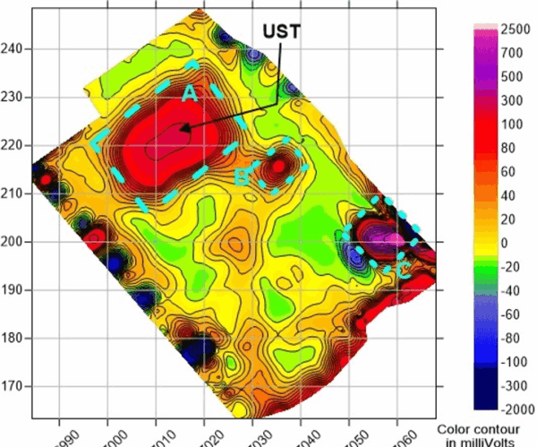
UST
For most UST investigations, utilizing an EM-61 shallow focus metal detector is the best choice; however, there are cases where 3D GPR is a better choice. The method chosen depends on the anticipated depth to and composition of the UST, as well as sources of interference (such as buildings, reinforced paving, fences and high voltage areas). Regardless of the method chosen, data are collected along parallel lines and color contoured to create plan view maps of signal response. In addition, utility locating methods are used to identify potential fuel and vent lines typically associated with USTs. If access to the UST can be obtained, Spectrum can use a Proprietary Method to determine the dimensions of the UST.
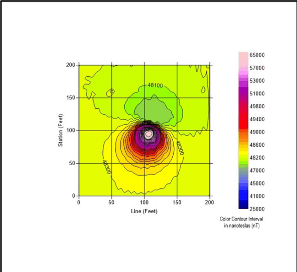
Oil Well
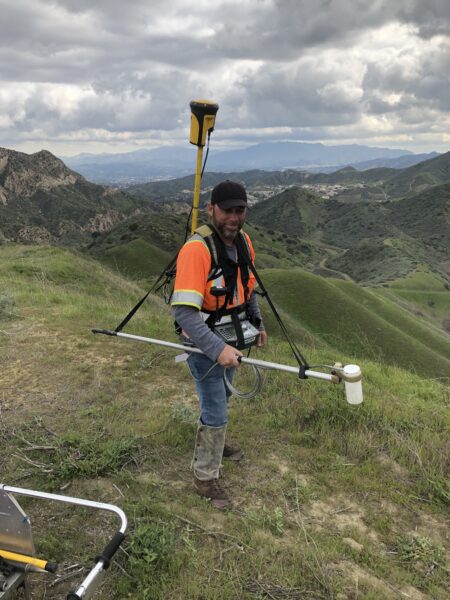
For most oil well surveys, utilizing a cesium vapor walking magnetometer is the best choice for detecting steel-cased oil or water wells. There are cases where a walking gradiometer or electromagnetics can be useful as well. The method chosen depends primarily on the anticipated depth to the top of the well, size of the area of investigation, and sources of interference (such as buildings, above-ground electrical facilities, metallic trailers, etc.) in the area of investigation. Other factors include what the well is constructed of, the vintage of the well, and reason for the survey (i.e. is there concern about brines or other types of soil or groundwater contamination).
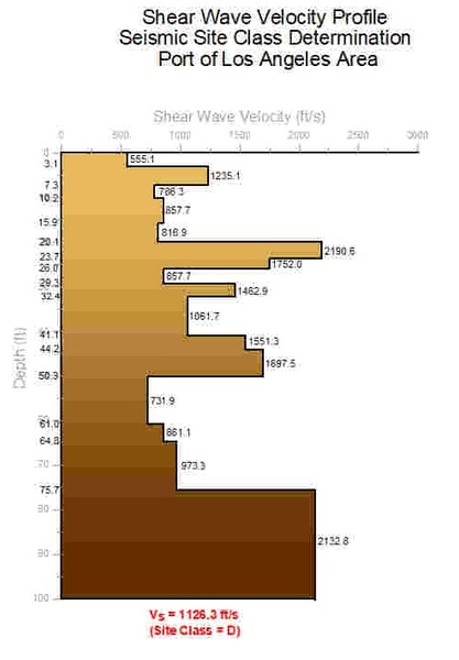
Seismic Site Classification (Vs30)
For most geotechnical investigations requiring the Vs30 parameter, or average shear wave velocity in the upper 30 meters of the ground surface, the active source ReMi (refraction microtremor) technique is the best choice. This method uses surface waves and ambient noise to generate a 1D vertical profile of the shear wave velocity and to measure the NEHRP seismic site class of the soils and rock at a site. Depending on several factors, such as space limitations, noise sources and RFP requirements, MASW or downhole seismic methods can be used as well. Spectrum typically collects p-wave seismic refraction data during ReMi surveys, to provide ground truth during data processing. A Proprietary Method using forward modeling is then utilized to generate the 1D shear wave velocity model. Once generated, this 1D profile and the seismic site class can then be used for earthquake design ground motion determinations in accordance with CBC 2022 and IBC 2021.
Paleochannel
Depending on a number of factors, electrical resistivity, seismic refraction, seismic reflection, EM-31 or TEM (or a combination of these) can be used for paleochannel investigations. The method(s) chosen depends on a number of factors including dimensions of the area of investigation, anticipated width and depth of the paleochannel in the study area, desired resolution of the paleochannel, lithology and expected competence of bedrock (i.e. sedimentary vs. igneous), expected composition of channel deposits (i.e. coarse sands, gravels, cobbles etc.), depth to groundwater in the area of investigation, and cultural features/sources of interference in the area of investigation.
Landfill
Defining the lateral extents and the depth of former landfills can be done using EM-31, magnetics and/or electrical resistivity. The method chosen depends on several factors, such as whether lateral or vertical delineation is required, the dimensions of the area of investigation, anticipated depth of landfill materials, lithology of background materials, anticipated type of landfill materials, and cultural features/sources of interference in the area of investigation.
Rebar Location
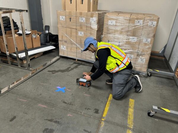
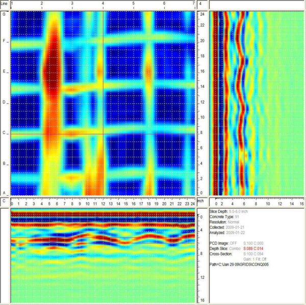
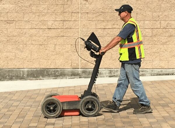
Utilizing the capabilities of ground penetrating radar (GPR) rebar location can be done in a safe and non-invasive fashion. No evacuation of tenants or workers is necessary. Microwave radiation emitted is less than that produced by a cell phone. Using either the GSSI structure scan or Sensors & Software Conquest system we can improve the safety of your project by identifying post tension cables, reinforcement, live electric lines buried in slabs and walls and verify the density of reinforcement in columns, slabs, and walls. With this method a 2-foot by 2-foot area can be scanned in less than an hour providing immediate results.
There are a few precautionary and/or ‘road’ rules to keep in mind. Green concrete and Robertson decking impedes radar penetration. The scanned area must be at least 3 inches away from obstructions. Multiple layers of rebar are difficult to detect if they are closely aligned with the layer above. Tile, grout, insulation, and roofing materials layered above the concrete strongly attenuate the radar signal. The size (or diameter) of reinforcement cannot be determined from the GPR scan.
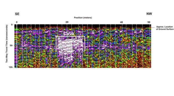
Void/Sinkhole Delineation
Our expertise in multiple different geophysical methods gives us the ability to investigate several different types of voids including shallow sinkholes, tunnels, voids in concrete, voids beneath shallow pipes, and shallow caves. The method chosen depends on a number of factors such as the depth and size of anticipated voids, reason for delineating voids, desired resolution of voids, nature of background materials or bedrock surrounding the voids, type of materials that may fill the voids (such as clay or water), depth to groundwater, size of the investigation area and sources of cultural interference in the investigation area. Spectrum commonly uses GPR, electrical resistivity, and EM-31 for void detection.
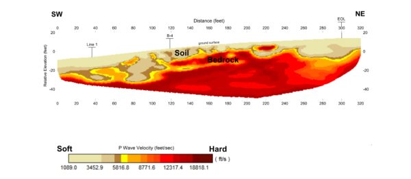
Depth to Bedrock/Rippability
Defining depth to bedrock depends on a number of factors including dimensions of the area of investigation, depth of investigation, desired resolution of overburden/bedrock interface, type of bedrock (i.e. sedimentary vs. igneous) and expected contrast with overburden, expected induration of bedrock, depth to groundwater, cultural features, and sources of noise or interference in the area of investigation. Utilizing seismic refraction, ReMi, MASW and/or electrical resistivity, we will tailor the approach to the scope of work provided.
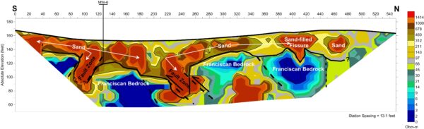
Fault Location
Living in California, delineating faults is obviously incredibly important to many projects. Depending on a number of factors such as dimensions of the area of investigation, depth of investigation, formation lithology on either side of the fault, degree of induration of layers in the formation, depth to groundwater, cultural features, and sources of noise in the area of investigation we will choose the best method to provide the desired results. Primary methods used are seismic refraction, electrical resistivity and seismic reflection. Achieving depths of over 1000ft in some cases, we can provide a breadth of experience unlike many in the industry.
Contaminant Plume Delineation
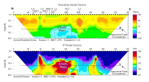
Utilizing electrical resistivity, TEM, EM-31, and/or EM-34 we can delineate such plumes including TDS plumes, LNAPL plumes, DNAPL plumes, chemical plumes, landfill plumes, and saltwater plumes.
The electrical resistivity/IP method is useful for the vertical (and lateral) delineation of plumes where the concentration of the contaminant in soil or groundwater is high enough to alter the natural electrical resistivity of the material to create a measureable change in resistivity when compared with background “clean” soils.
Time domain is especially useful where the plume is deep (greater than 200 feet), the space for investigation is small (precludes the use of DC resistivity), or where there is a large area to investigate, as many 1-D measurements can be made quickly and relatively cheaply.
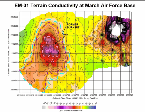
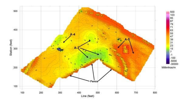
Frequency domain methods are especially useful where there is a large area to investigate, as an extremely large number of measurements can be made quickly and cost effectively. Spectrum commonly uses the Geonics EM-31 (near-surface) or EM-34 (depths up to 60 meters) terrain conductivity meters for frequency domain methods.
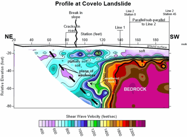
Loose/Weak Soil Delineation
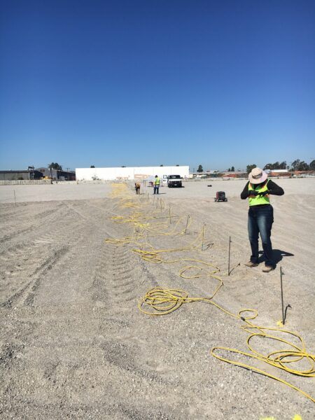
Delineation of areas of loose/weak soil or fractured rock is typically accomplished using 2D multichannel analysis of the surface wave (MASW), along with detailed p-wave refraction tomography. These methods provide lateral and vertical measurement of the shear wave and p-wave velocity and can be used for a wide variety of geotechnical applications such as bridge and dam design, delineation of buried slide planes, or delineation of areas prone to liquefaction. However, depending on site limitations such as noisy environments, orientation/nature of subsurface features of interest, and desired depth of investigation, electrical resistivity tomography (ERT) may also be used. Regardless of the method chosen, a transect is typically established along the ground surface, where a linear array of geophones (or electrodes) is used to collect the data. Once processed, the data are presented in a 2D profile and interpreted for features of interest. Depending on the methods implemented, the profiles can be used to calculate standard engineering parameters, such as shear modulus and Poisson’s ratio.
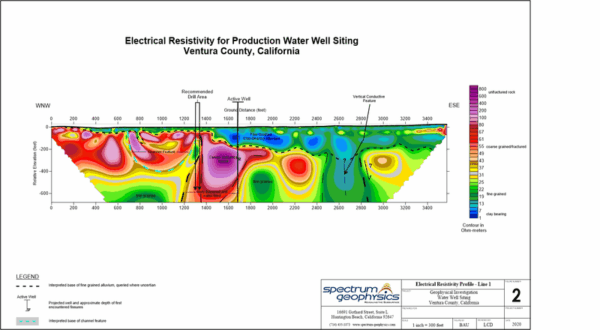
Groundwater Delineation
Delineation of groundwater, or aquifers vs aquicludes in the subsurface, is usually accomplished using electrical resistivity tomography (ERT) or time domain electromagnetics (TDEM). The method chosen depends on several factors, such as nature of (i.e. alluvial aquifer or water bearing fractures in rock) and anticipated depth of groundwater, groundwater salinity, size of the investigation area, purpose for delineation, and budget constraints. Typically, a linear transect is established to collect the data, and resultant profiles can be used to identify the depth to potentially saturated zones for production water well siting, preferential pathways for groundwater, areas where perched water may be present, or areas of high TDS/high salinity groundwater.